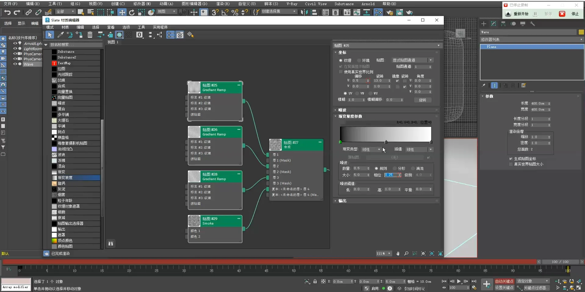
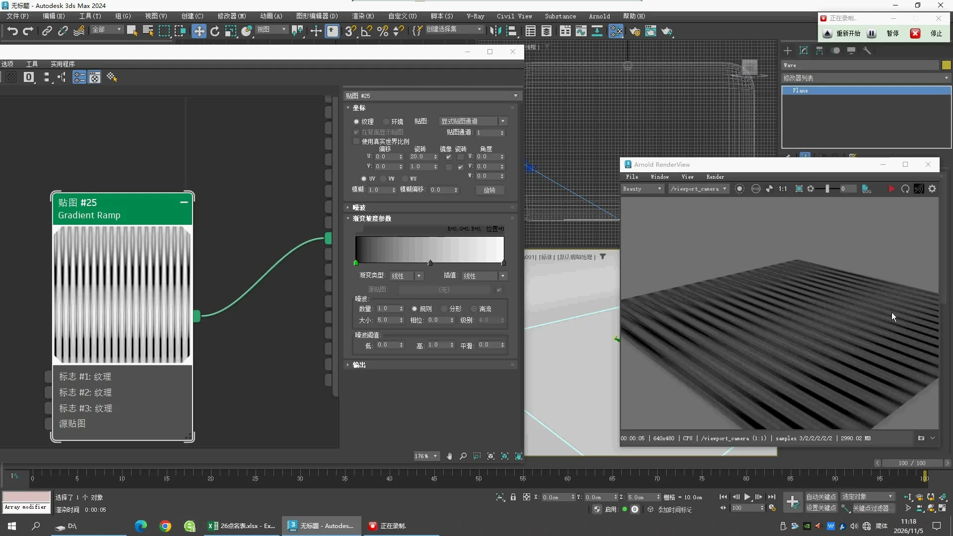
Gradient Ramp #25 — copy the visible values
This screenshot shows frame 100. These are visible values at that frame, not a recovered animation curve. This is the linear-water branch, not the earlier radial-ring recipe.
| Panel / Parameter | Visible value |
|---|
| Coordinates → Mapping / Map Channel | Explicit Map Channel / 1 |
| Coordinates → U Offset / V Offset | 0.5 / 0.0 |
| Coordinates → U Tiling / V Tiling | 13.0 / 1.0 |
| Coordinates → U Mirror | On |
| Coordinates → U / V / W Angle | 0.0 / 0.0 / 0.0 |
| Coordinates → Blur / Blur Offset | 1.0 / 0.0 |
| Gradient Type / Interpolation | Linear / Linear |
| Selected left flag | Position 0; RGB 0, 0, 0 |
| Noise → Amount / Size | 0.5 / 5.0 |
| Noise → Type / Phase | Regular / 0.25 |
| Noise → Levels | 4.0 shown disabled |
| Noise Threshold → Low / High / Smooth | 0.0 / 1.0 / 0.0 |
Understand it with three small changes
- For a separate practice copy, keep Auto Key OFF. Set Noise Amount = 0 and U Tiling = 1. Preview this map on the Plane to isolate the gradient.
- Set U Tiling = 13, with U Mirror ON: the gradient repeats and reverses direction between repeats, producing bands.
- Restore Noise Amount = 0.5, Size = 5, Phase = 0.25. Compare the texture with the clean bands. Change only one value at a time.
U Offset shifts the texture across the surface. Phase changes the noise pattern. Neither parameter moves the Plane itself. The screenshot shows Auto Key on and red animation markers, but does not establish the starting values or curve tangents.
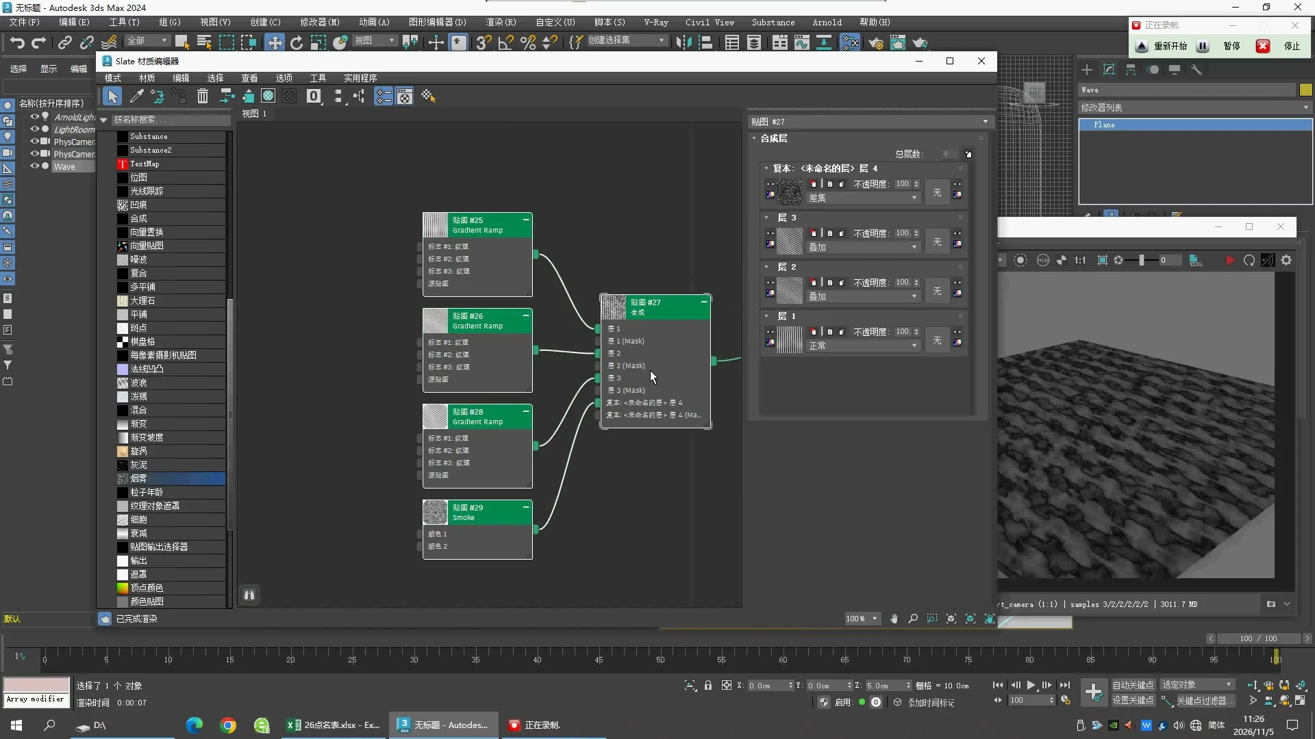
Visible connection: #25 → Composite #27 Layer 1; #26 → Layer 2; #28 → Layer 3; Smoke #29 → Layer 4. The Composite blend modes, other gradient flags, and other maps' settings remain unverified. Do not fill them in as teacher values.
Plane: Length 400 cm, Width 400 cm, Length Segs 1, Width Segs 1, Generate Mapping Coords on. This screenshot alone does not establish a displacement setup.
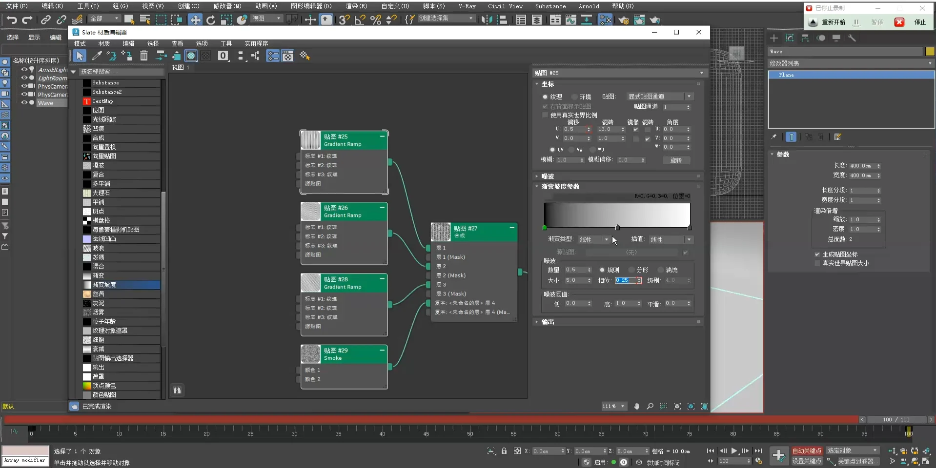
Gradient Ramp #25 — your Frame 100 screenshot
This is an additional observed state, not a verified animation. The existing static MAX study uses U Offset 0 and Phase 0; this screenshot shows 0.5 and 0.25. A separate saved-and-reloaded scene now matches these two values: Download Frame 100 study. No animation keys were inferred. Readback.
| Parameter | Visible value | What to look for |
|---|
| U Tiling / V Tiling | 13 / 1 | U Tiling controls repetition along U. More repetition makes the bands closer together. |
| U Offset / V Offset | 0.5 / 0 | Changes where the pattern is sampled; it does not move the Plane. |
| U Mirror / U Tile | On / Off | Alternates the direction of repeated gradients. |
| V Mirror / V Tile | Off / On | Normal repetition along V. |
| U / V / W Angle | 0 / 0 / 0 | No coordinate rotation in this node. |
| Gradient Type / Interpolation | Linear / Linear | A straight black-to-white gradient with linear transitions. |
| Noise Amount / Type | 0.5 / Regular | Adds variation to the gradient; compare with Amount 0 to see its contribution. |
| Noise Size / Phase | 5 / 0.25 | Size controls the scale of variation. Phase changes the noise pattern; a constant Phase is not motion. |
| Noise Threshold Low / High / Smooth | 0 / 1 / 0 | Visible threshold settings. |
先理解这三个参数:U Tiling = 条纹重复得多密;U Offset = 条纹移到哪个位置;Noise Phase = 噪波呈现哪一种形态。改变 Offset 不会移动 Plane。单张图只能确认当前值,不能确认完整动画。
Try this: save a separate copy, turn Auto Key off, double-click Gradient Ramp #25, set U Offset to 0.5 and Noise Phase to 0.25, then render. Change one value at a time. Compare Amount 0 versus 0.5 first; restore 0.5 afterward. This reproduces the visible parameter state only, not the whole teacher render.
Frame 100 and the red Auto Key interface are visible, but the screenshot does not establish the first key, intermediate keys, or interpolation. Do not assume a 0 → 0.5 Offset animation or a 0 → 0.25 Phase animation is confirmed.
Build the linear water material
本次核对覆盖全片的 79 个约 10 秒间隔抽样,并放大检查关键设置;另附精确时间定位截图。尚不是每帧审阅。下面按教师制作顺序整理,并明确区分中途试验、后期保留值及补齐值。
Editable Arnold scene Material library
1. Plane + Arnold Standard Surface
Create a Plane: Length 400 cm, Width 400 cm, Length Segs 1, Width Segs 1, Z 5 cm; enable Generate Mapping Coords. Assign an Arnold Standard Surface: Base 0, Specular 0, Emission 0.5. This chapter draws the water pattern using Emission Color; a fine mesh is not needed for that color pattern.
2. Make the first bands
Add Gradient Ramp #25. Set Gradient Type = Linear, Interpolation = Linear, Explicit Map Channel 1. Black at 0, neutral gray at 50, white at 100. The exact middle RGB was not opened: the study uses 127.5/127.5/127.5 as a supplemental value.
| Parameter | #25 | #26 | #28 |
|---|
| U Tiling | 13 | 19 | 15 |
| V Tiling | 1 | 1 | 1 |
| W Angle | 0° | 30° | 60° |
| U Mirror / U Tile | On / Off |
| V Mirror / V Tile | Off / On |
| Noise Type / Amount / Size | Regular / 0.5 / 5.0 |
| U Offset / V Offset / Noise Phase | 0 / 0 / 0 in this static chapter |
The earlier demonstration uses U Tiling 20 and Noise Amount 1.0. These are intermediate values, not the later settings above. Your screenshot with U Offset 0.5 and Phase 0.25 shows a different state; it remains documented below and is not silently mixed into this static reconstruction.
U Tiling changes spacing. W Angle rotates the stripes on the Plane. Noise Amount changes the clean gradient pattern. Copy #25 to create #26 and #28, then change their Tiling and W Angle.
3. Combine the three directions
Add Composite #27. Connect #25 to Layer 1, #26 to Layer 2, #28 to Layer 3. Use Normal / Overlay / Overlay, all Layer Opacity 100%. The crossed patterns break the single-direction stripes into smaller shapes.
4. Add Smoke as the fourth layer
Add Smoke #29: Coordinates = Explicit Map Channel 1, Size 0.05, Iterations 5, Exponent 1.0, Phase 0, black/white colors. Connect it to Composite Layer 4. The last visible mode is Difference, at 100%.
The teacher first tries Object XYZ and much larger Size values, then switches to Explicit Map Channel and smaller sizes. Size 101.6 in Object XYZ and Size 0.05 in UV coordinates are different sampling setups; do not copy one number while keeping the other coordinate system.
5. Map the grayscale pattern to blue
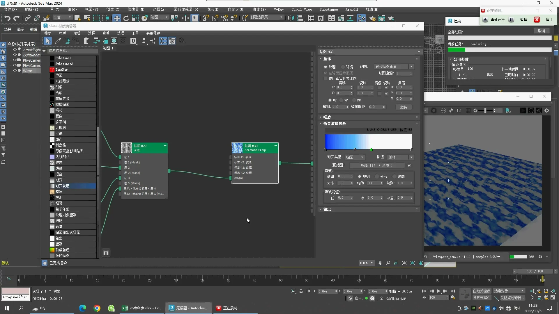
Add Gradient Ramp #30, set Gradient Type = Mapped. Connect Composite #27 to its Source Map; connect #30 to the material's Emission Color. Interpolation stays Linear, Noise Amount 0.
Visible later flags: Position 34 → RGB (28,137,255); Position 53 → RGB (248,253,255). Right endpoint remains white. The left blue endpoint is not fully confirmed: this study uses RGB (0,12,255). These RGB values are the ramp's numeric values, not a sampled screenshot color.
#25 ─ Normal ─┐
#26 ─ Overlay ┤
#28 ─ Overlay ┤ Composite #27 → Source Map of #30 → Emission Color
#29 ─ Difference ┘
Verified in the Max interface
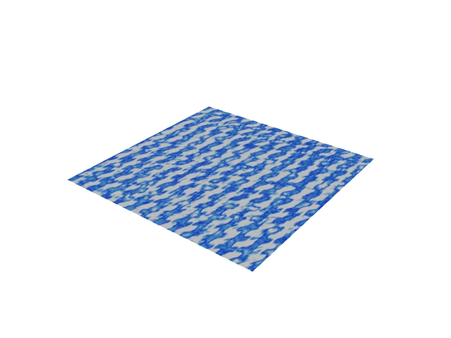
The saved scene was opened in the existing Max window. F9 opened Arnold RenderView; its Start Render button produced the image, exported using File → Save Image. The scene itself was constructed by script.
See each stage
These batch renders share the same camera and material Emission weight. Only the map connected to Emission Color changes. The batch renderer added an Arnold license watermark; these are diagnostic comparisons, not final submission images. The interface render above was exported separately.
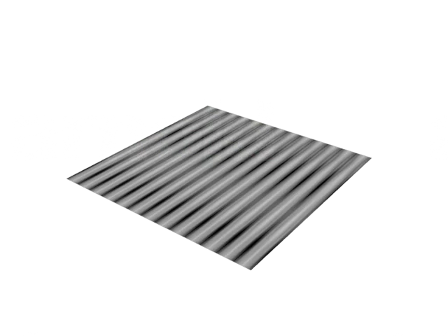 1 · #25 only: repeated bands
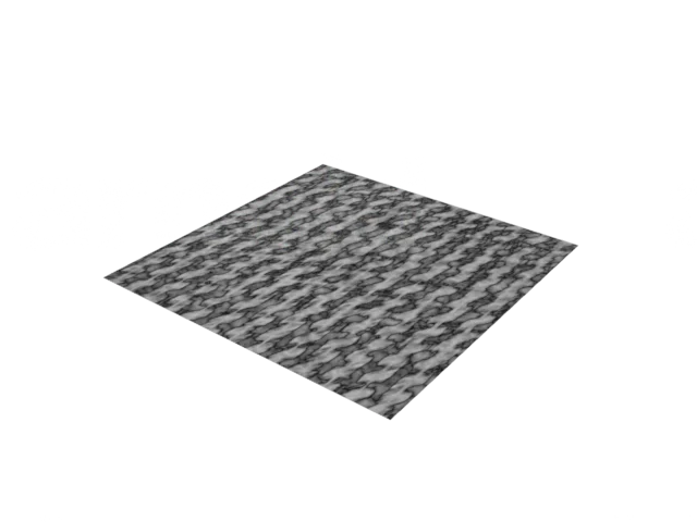 2 · #27: crossed bands + Smoke
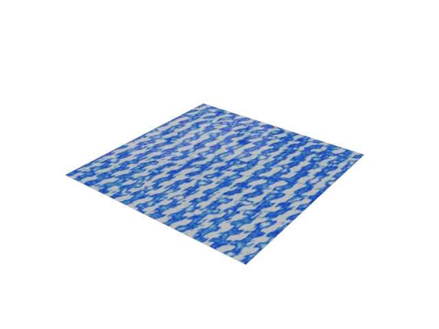 3 · #30: grayscale becomes blue
What is still supplemental?
The camera (520, −680, 510 cm), viewing toward (0,0,5), FOV 45°, and gray background are supplied viewing settings. The teacher's LightRoom, lights, cameras, exposure and the following chapter's animation are not recovered here. This static study is not a completed water-drop assessment.
Open the MAX file and press F9. If Arnold RenderView is gray, click its Start Render triangle. For an experiment, temporarily set Layer 4 Opacity to 0, render, then restore 100: this isolates what Smoke contributes. Keep Auto Key OFF for the experiment.
Saved-scene readback and estimated settings · Autodesk: Composite blend mode names
Check the original video
03:35 · Earlier #25 trial: Tiling 20
06:25 · #26: Tiling 19
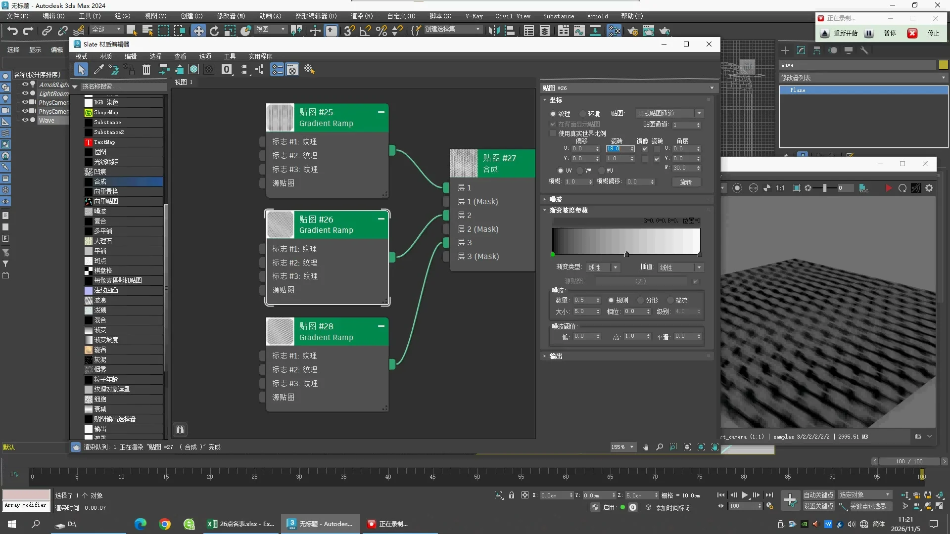
06:35 · #25: Tiling 13, Amount 0.5
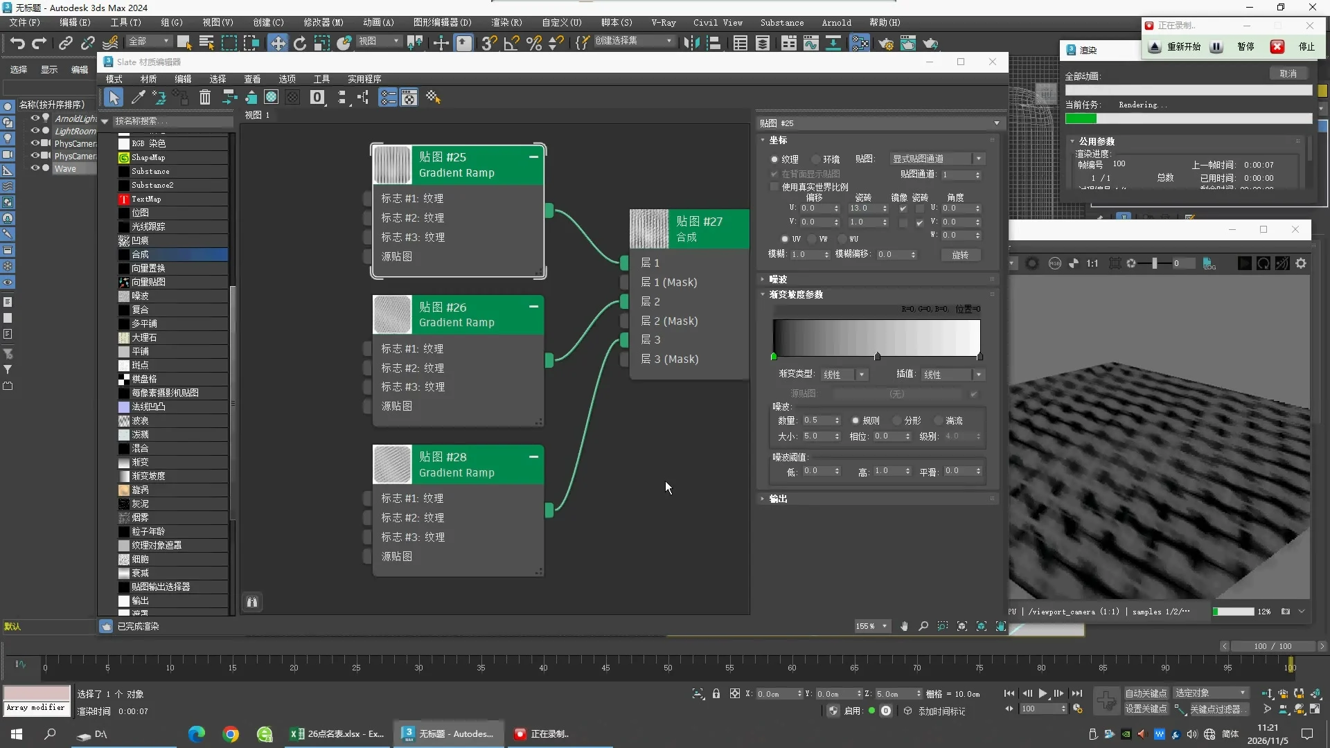
06:55 · #28: Tiling 15, Angle 60
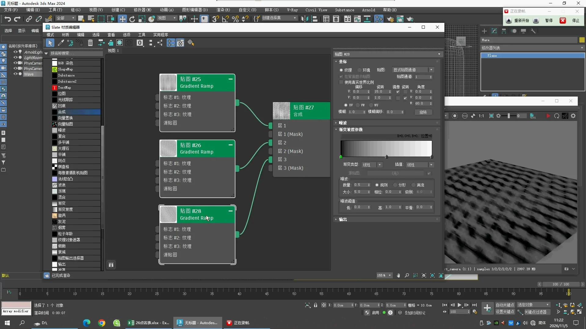
10:45 · Smoke: UV coordinates and Size 0.05
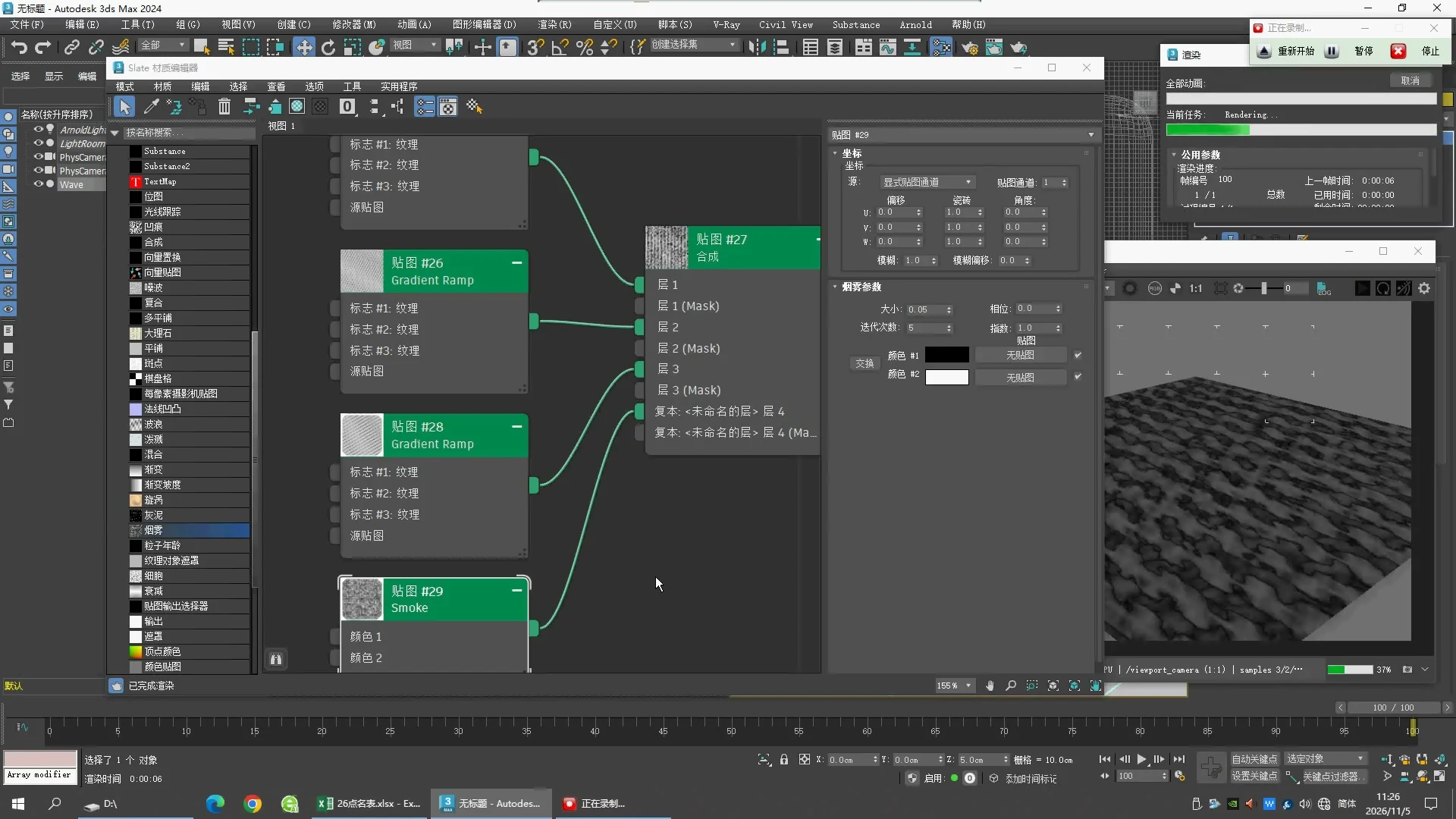
11:15 · Composite: Difference on Layer 4
12:35 · Color flag at Position 34
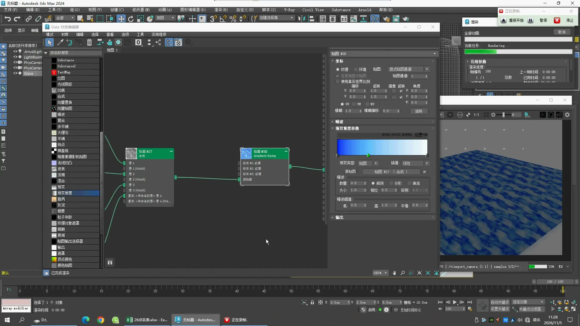
13:04 · Color flag at Position 53