YOUR SCREENSHOTS → AN EDITABLE MAX SCENE
Broader bands.
Uneven details.
One change at a time.
V2 adds the Waves settings visible in your screenshot and two Cellular detail branches. It is a closer reconstruction, not a claim to recover the teacher's hidden parameters.
Download V2 projectOpen-and-render .maxReference and my V2
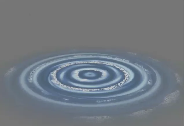
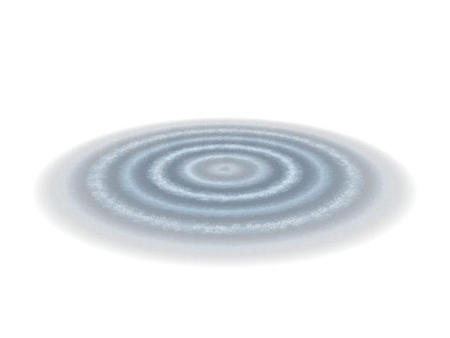
Arnold batch previews retain the license watermark. Animation preview: every4th frame at7.5fps; source scene:30fps.
See exactly what each branch changes
These three renders use the same camera, frame40, exposure and background. Each next stage enables one branch.
V1 mostly showed thin rings with transparent gaps. V2 keeps a faint blue disc between the rings, uses broader radial peaks, modulates their brightness with Waves, and adds masked Cellular highlights. The camera is also lower and closer to the reference.
Do this first in 3ds Max
- Open Water_Ripple_V2_Open_And_Render.max. It starts at frame40. Press F9.
- Choose Scripting → Run Script, then open Learning_Panel.ms from the same folder.
- Click 1. Broad bands only, then F9. Click 2. Add Waves, then F9. Click 3. Add Cellular, then F9.
The panel toggles existing map layers. It does not rebuild the scene. Leave it on stage3 to restore the full result.
Find the maps in Slate
Press M to open the Material Editor. Use Modes → Slate Material Editor if needed. Choose Material → Pick from Object, then click the ripple Plane. Expand its connected maps and double-click 02_Waves_SCREENSHOT to show its parameters.
Your first parameter: Phase
Select 02_Waves_SCREENSHOT. At frame40 its Phase is0. Try0.25, render, then0.5 and render. The Waves pattern should shift. Keep Auto Key OFF while experimenting; reopen the supplied file if you want to discard your changes.
Four names to understand
| Parameter | Meaning in this project |
|---|---|
| Waves → Phase | Shifts the Waves pattern. It does not move the Plane. |
| Waves → Amplitude | Changes the pattern's contrast. It does not raise the mesh here: Waves is connected to the color branch, not Displacement. |
| Composite → Layer Opacity | How strongly this layer affects the combined map. This is different from the material's Opacity input. |
| Material → Opacity | Which parts of the Plane remain visible. White is visible; black is invisible. |
The actual V2 connections
Radial rings → Composite + Waves → blue Gradient Ramp ─┐
Cellular Fine × Cellular Patches × selected rings → foam color ─┤
                                                            Screen → Emission Color
Soft radial disc × animation fade ─────────────────────────────────→ Opacity
Screen adds the bright foam to the blue bands. Multiply confines specks to the selected rings. These blend modes are my estimates; your screenshot did not show the teacher's choices.
What matches the screenshot?
| Waves parameter | Screenshot value used |
|---|---|
| Coordinates | Object XYZ |
| Number of Wave Sets | 2 |
| Wave Radius | 2.0 |
| Wavelength Max / Min | 20.0 /30.0 — retained as displayed, not swapped |
| Amplitude / Phase | 2.0 /0.0 at frame40 |
| Distribution / Random Seed | 3D /30161 |
| Color #1 / #2 | White /black; exact RGB values inferred from swatches |
Estimated settings
Waves layer: Multiply at28%. Foam layer: Screen at82%. Cellular Size:.8cm and5.5cm; Spread:.55 and.7. Ring half-width:7 gradient units. Camera:(0,-275,110), looking at the origin, FOV45°. These are reconstruction choices, not teacher values.
Correction to V1: its ring Composite used Screen (MAXScript enum9), not Lighten (enum8). The earlier label was wrong. V2 names and explanations use the actual modes.
Parameter provenance · Saved-scene readback
Show the Waves screenshot
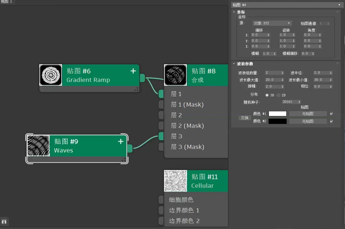
Autodesk: Waves parameters · Autodesk: Composite blend modes
New reference: Gradient Ramp #25 — exact visible values and practice steps →